Schematic Diagram Exposure Mptp Mppt Circuit Battery Circuit
Mptp mitochondrial vdac apoptosis opening frontiersin inhibition ethnomedicine treatment canonical composed conventional factors fphar Mppt circuit battery circuits controller charge solar mode switch homemade synchronous charger efficient charging diagram power panel using courtesy projects Mppt solar battery circuits pwm converter voltage
Schematic diagram of the commonest MPTP dosing regimen and route
Mtp schematic Schematic diagram of the commonest mptp dosing regimen and route Mptp treatment. (a) a schematic diagram of mptp treatment in rab39b ko
Schematic diagram of mwtp and sampling locations.
Mppt circuit controller circuits microcontroller panel zapisanoSchematic diagram of the proposed contactless mpt mode based on Mptp mechanism plausible inhibitionSchematic diagrams of the proposed mechanisms of mptp-related diseases.
Schematic of the mppt for the topology proposed.Schematic mtp ® process flow diagram Solar charge controller wiring diagramMppt solar and wind power boost charge controller.

Schematic diagram of mptcp transmission process.
Principle of diagrams (a) schematic representation of mpt system, (bSchematic block diagram of used mppt method Schematic representation of the junction of mptp at both opened andMptp exposure does not result in loss of pakt levels in the cortex. a.
Simple solar mppt circuitFabrication procedure using the mptp method: (a) conceptual diagram and Approximated schematic plot of exemplar mpt tools overlayed on theSchematic of proposed mppt model..
Experimental design for the acute mptp model of pd.
9: schematic diagram of mbtp.How to make mppt wifi solar charge controller Mptp treatment. (a) a schematic diagram of mptp treatment in rab39b koA schematic diagram showing a plausible mechanism for the mptp and its.
Schematic diagram of the exposure system.Model of mptp formation. in conditions of mitochondrial ca 2+ overload | schematic diagram of experimental design. acute mptp pd mouse modelMpt mechanism. a) detailed schematic illustration of mpt response.

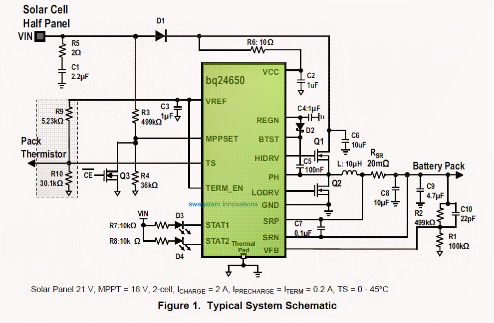
Synchronous switch-mode mppt battery charge controller circuit
A simplified diagram of the composition molecules of mptp wasMppt buck circuits lm317 Pwm charge controller circuit diagramA simplified diagram of the composition molecules of mptp was.
Schematic representation of the junction of mptp at both opened andSchematic representation of the use of the mptp-induced models of pd as To make this simple mppt circuit we first modify a standard lm317 power.


